
What is a three winding transformer? Difference between three windings in a transformer?


Table of contents:
1. What is three windings transformer
2. What is the difference between three windings of a transformer
3. The advantage of tertiary winding
4. Equivalent circuit of a three winding transformer
5. The Parameters of Three-Windings Transformers
1. What is three windings transformer?
In some high-rating transformer, one winding is added to its primary and secondary winding. This additional winding, different from primary and secondary windings, is known as Tertiary winding or third winding of transformer. Because of this Tertiary winding, the transformer is called three winding transformer or 3-winding transformer.
Reference article:
Difference between power and distribution transformer
Difference between step up and step down transformer
Distribution transformer design
2. What is the difference between three windings of a transformer
The voltage ratings of all three windings of a transformer are usually not equal. Specifically, the primary winding has the highest voltage rating; the third has the lowest voltage rating, and the secondary has an intermediate voltage rating.
![]()
3. The advantage of the tertiary winding
The third winding is provided in the electric transformer to meet one or more of the following requirements:
- It reduces the unbalance in the primary due to unbalance in three-phase loads.
- It redistributes the flow of the fault current.
- Sometimes the transformer is required to supply an auxiliary load in different voltage levels and the main secondary load. This secondary load can be taken from the tertiary winding of three winding transformers.
- Because the tertiary winding is connected in delta formation in 3 winding transformer, it help to prevent fault current in the event of a short circuit from line to neutral.
4. Equivalent circuit of a three winding transformer
The circuit diagram of the three-phase transformer is shown in the below figure. Consider that the R1, R2 and R3 are the resistance and the X1, X2 and X3 are the impedance of their windings.
The V1, V2, V3 are the voltages and the I1, I2, I3 are the current flows through their windings.
5. The Parameters of Three-Windings Transformers
The specification of the equivalent circuit can be showed from the open circuit and the three short-circuit tests.
Short Circuit Test
Consider the Z1, Z2 and Z3 are the impedances of the 3 winding transformers. They are considered as the base for performing the short circuit test. For the short-circuit test, the two winding is short circuit, and the third winding is kept open.
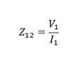
In the first step, consider winding 1 and 2 to be shorted. The low-voltage winding is applied to coil 1 due to the full-load current flowing through coil 2. Z12 denotes the impedance of coils 1 and 2, and it is measured by
Equivalent resistance,
![]()
Equivalent leakage reactance,
![]()
The Z12 is the series combination of Z1 and Z2 respectively,
![]()
![]()
In the second step, the third is short-circuited with the second and the primary held open. The low voltage supply is placed on the third coil so that full load current flows through the second. Z23 represents the impedance of coils 2 and 3 and the equation below represents it
![]()
In the third step, the second winding is opened, and the first and the third windings are short-circuited. Low voltage is applied to the third coil and full load current flows through the first windings. Z13 is the impedance of the first and third winding.
![]()
Equivalent-circuit of a-three coil-transformer Solving equations (1), (2) and (3) we get the leakage impedances Z1, Z2 and Z3, all called the primary,
![]()
Open circuit test
An open-circuit test is performed to determine core loss, magnetizing impedance and turn ratio. In the open-circuit test, a voltmeter, ammeter and a wattmeter are connected in the low-voltage winding. The secondary side is kept open, and the voltmeter is connected.
Since the high-voltage side is open, the current drawn by the primary winding is the no-load current, and I0 is measured with the ammeter A. The magnetic impedance can be found when the current winding excites 1 with both windings 2 and 3. are open circuits. Then we have,
![]()
The voltage adjustment of a three-winding transformer is defined as the ratio of the magnitude of the actual winding load kVA to the base kVA used to determine network parameters.