SFRA is a very reliable and sensitive method or tool to measure the condition of the windings, core, and clamping structures within power transformers.
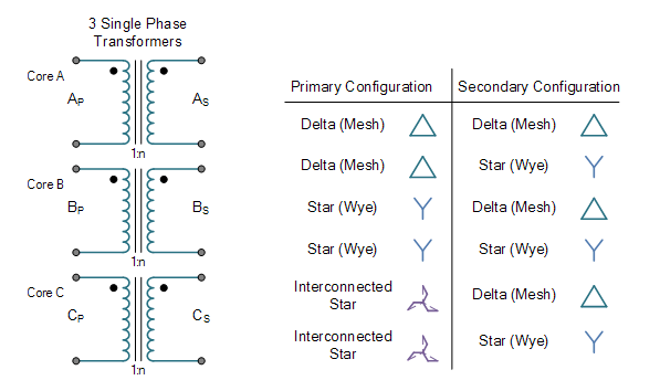
The connection of the primary and secondary winding of a three-phase transformer can be designed in different ways according to the desired application and available terminals.
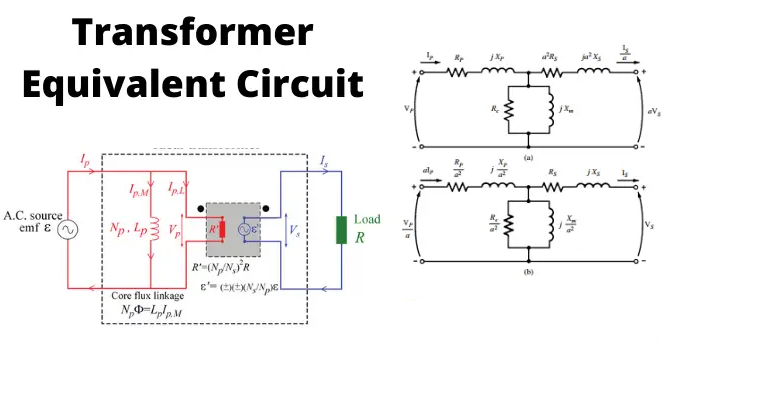
The equivalent circuit diagram of a transformer is a simplified circuit in which the impedance, resistance, and leakage reactance of the transformer can be more easily calculated.
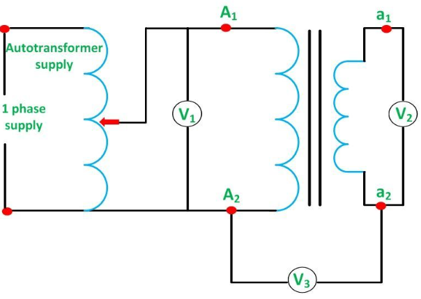
The polarity can be defined as the induced voltage direction in the primary windings and the secondary winding. If two transformers can be connected in parallel, then the polarity must be identified for a good connection of the transformer.
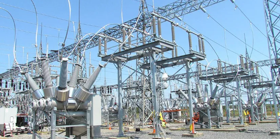
This article will introduce a few most common types of MV/HV power substations based on the type of distribution switchgear, which can be seen in every distribution network. There are a number of methods of construction of substations depending on the switchgear type.
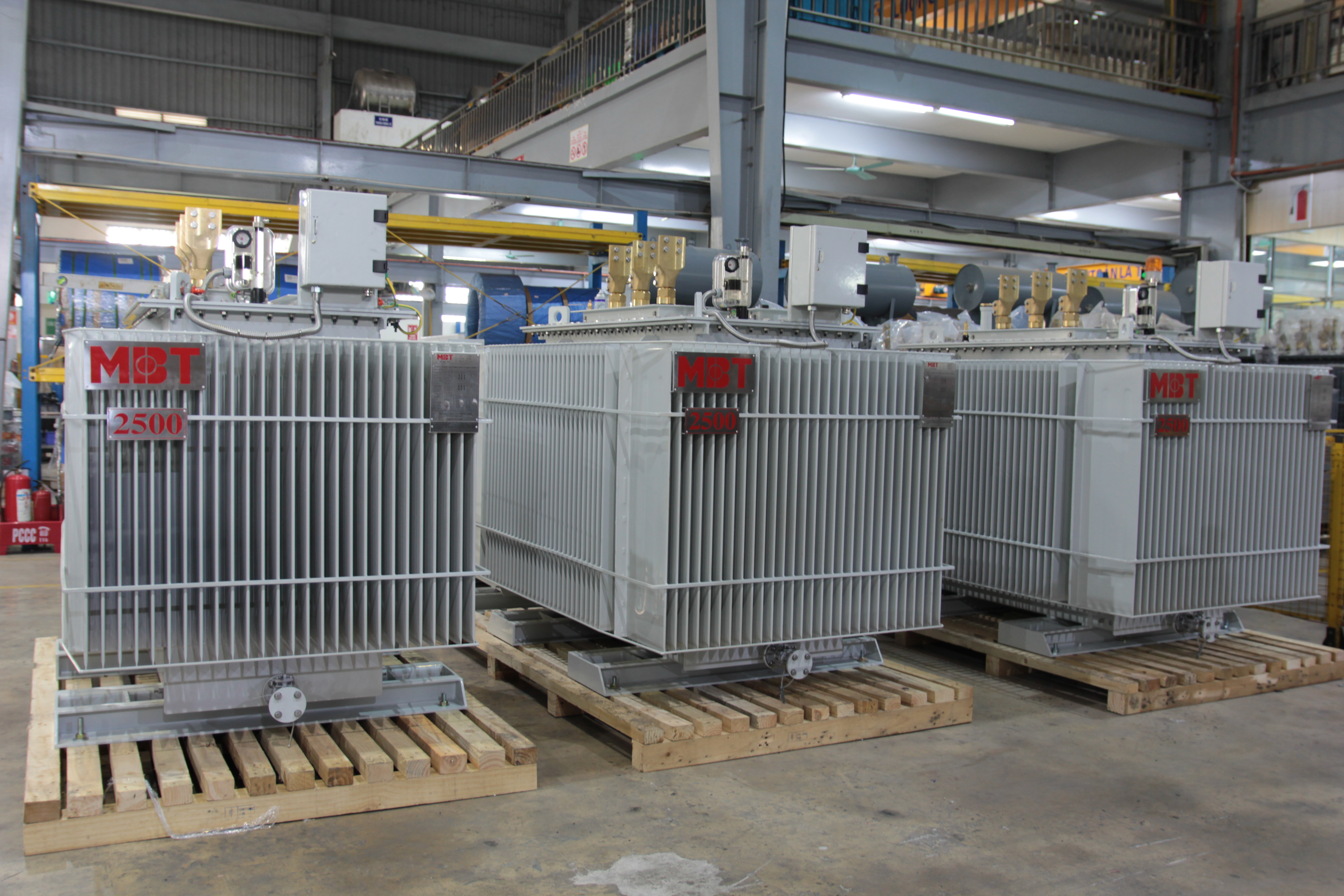

 913006538 info@mbt.vn mbt transformer vietnamtransformer.vn (1).png)