
Transformer Voltage and Current


Transformer Voltage and Current
If the small amount of transformer loss is ignored, the back-voltage (back EMF) of the primary must equal the applied voltage. The magnetic field, which induces the back-voltage in the primary, also cuts the secondary coil. If the secondary coil has the same number of turns as the primary, the voltage induced in the secondary will equal the back-voltage induced in the primary (or the applied voltage). If the secondary coil has twice as many turns as the primary, it will be cut twice as many times by the flux, and twice the applied primary voltage will be induced in the secondary. The total induced voltage in each winding is proportional to the number of turns in that winding. If E1 is the primary voltage and I1 the primary current, E2 is the secondary voltage and I2 the secondary current, N1 the primary turns and N2 the secondary turns, then:
E1/E2 = N1/N2 = I2/I1
Note that the current is inversely proportional to both voltage and the number of turns. This means (as discussed earlier) that if the voltage is stepped up, the current must be stepped down and vice versa. The number of turns remains constant unless there is a tap changer (discussed later). The power output or input of a transformer equals volts times amperes (E x I). If the small amount of transformer loss is disregarded, input equals output or:
E1 x I1 = E2 x I2
Example
If the primary voltage of a transformer is 110 volts (V), the primary winding has 100 turns, and the secondary winding has 400 turns, then the secondary voltage will be:
E1/E2 = N1/N2; 110/E2 = 100/400; => E2 = 440 V
If the primary current is 20 amps, the secondary current will be:
E2 x I2 = E1 x I1; 440 x I2 = 110 x 20; => I2 = 5 A
Since there is a ratio of 1 to 4 between the turns in the primary and secondary circuits, there must be a ratio of 1 to 4 between the primary and secondary voltage and a ratio of 4 to 1 between the primary and secondary current. As voltage is stepped up, the current is stepped down, keeping volts multiplied by amps constant. This is referred to as “volt-amps.”
As mentioned earlier and further illustrated in Picture 1, when the number of turns or voltage on the secondary of a transformer is greater than that of the primary, it is known as a step-up transformer. When the number of turns or voltage on the secondary is less than that of the primary, it is known as a step-down transformer. A power transformer used to tie two systems together may feed current either way between systems, or act as a step-up or step-down transformer, depending on where power is being generated and where it is consumed. As mentioned above, either winding could be primary or secondary. To eliminate this confusion, in power generation, windings of transformers are often referred to as high-side and low-side windings, depending on the relative values of the voltages.
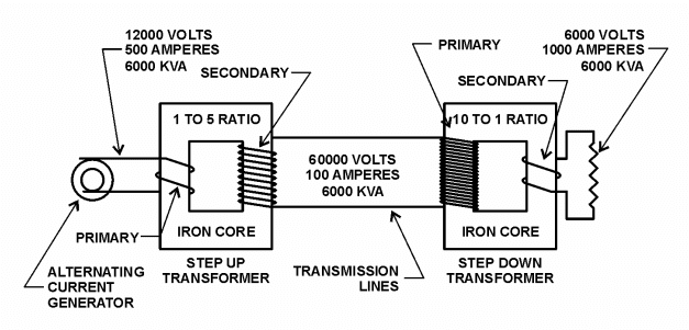
Picture 1: Step-Up and Step-Down Transformers
Note that kVA (amps times volts) remains constant throughout the above circuit on both sides of each transformer, which is why they are called constant wattage devices. Efficiencies of well-designed power transformers are very high, averaging over 98 percent (%). The only losses are due to core losses, maintaining the alternating magnetic field, resistance losses in the coils, and power used for cooling. The main reason for the high efficiencies of power transformers, compared to other equipment, is the absence of moving parts. Transformers are called static AC machines.
Copy: Blogspot