
Transformer Rating, Impedance, and Internal Forces


Transformer Rating, Impedance, and Internal Forces
Transformer Rating
The rating is the load-carrying capability of the machine and limited by the temperature that the insulation can withstand.
The increase in the rate is due to reducing core and copper losses, increasing the rate of heat dissipation (better cooling), or improving transformer insulation so it will tolerate higher temperatures.
The rating depends on the temperature of their windings and oil that reaches within the specified limit.
Due to the increase in the area and volume of oil, a physically larger transformer can dissipate more heat.
This means that a transformer must be worked with the “hottest spot” cooler than this degradation temperature, or service life is greatly decreased. Reclamation typically orders transformers larger than required, which aids in removing heat and increasing transformer life.
Ratings of transformers are achieved by simply multiplying the current times the voltage. “VA,” volts times amperes is used for the transformers with small rating. As for size increases, 1-kilovolt amperes (kVA) is equal to 1,000-volt-amperes, 1 mega volt-ampere (MVA) is equal to 1 million volt-amperes.
The rating Large GSUs could be hundreds of MVAs. The price of A GSU transformer can be over a million dollars and take 18 months to 2 years or longer to manufacture. Each one is designed for a specific application.
If one fails, this could mean a unit or entire plant could be shut down for 2 years, costing millions of dollars in lost power generation, in addition to the replacement cost of the transformer itself. This is a reason that proper maintenance is so important.
Percent Impedance
The impedance of a transformer is the total opposition of the alternating current. This can be calculated for each winding.
However, a fairly simple test provides a practical method of measuring the equivalent impedance of a transformer without separating the impedances of the windings.
To determine the equivalent impedance, one winding of the transformer is short-circuited and just enough voltage is applied to the other to induce a full-load current to flow in the short-circuited winding.
This voltage is known as the impedance voltage. Either winding could be short-circuited for this test, but it is usually more convenient to short-circuit the low-voltage winding. The impedance value of the transformer is marked on the nameplate in percent. This means that the voltage drop due to the impedance is shown as a percent of rated voltage. For instance, if a 2,400/240-volt transformer has a measured impedance voltage of 72 volts on the high voltage windings, its impedance (Z), expressed as a percent, is:
percent Z = (72/2400) x 100 = 3 %
It means there would be a 72-volt drop in the high-voltage winding at full load due to losses in the core and windings. Only 1 or 2% of the losses are caused by the core; about 98% are by the winding impedance. If the transformer were not worked at full load, the voltage drop could be less. If an actual impedance value in ohms is necessary for the high-voltage side:
Z = V/I
V is the voltage drop or, in this case, 72 volts; and I is the full load current in the primary winding. If the full load current is 10 amps:
Z = 72 V/ 10 A = 7.2 ohm
The impedance is created by both resistive and reactive components.
Internal Forces
During normal operation, internal structures and coils are subjected to mechanical forces due to magnetic forces. These forces are illustrated in Figure 1. By designing a very strong internal structure to withstand these forces for a long time, service life can be extended. However, in a large transformer where a "fault through" (fault current passing through the transformer) occurs, the force can be in the millions of pounds, pulling the windings up and down and pulling them away. 60 times per second. Notice in Figure 1 that the low voltage coil inside is being pulled down, while the high voltage coil is pulled up in the opposite direction. At the same time, the right part of the figure shows the high voltage coil and the low voltage coil being forced apart. Remember that these forces change direction 60 times per second. It is clear why the internal structure of the transformer must be built extremely solidly.
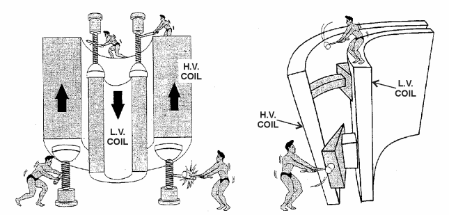
Picture 1: Transformer Internal Forces
If the fault current is high, these forces can rip apart the transformer and cause electrical failure inside the transformer. This often results in arcing inside the transformer, which can lead to a tank fire or explosion, spilling kerosene over a large area. A protective relay system is in place to protect against this possibility, although fires and explosions sometimes occur.
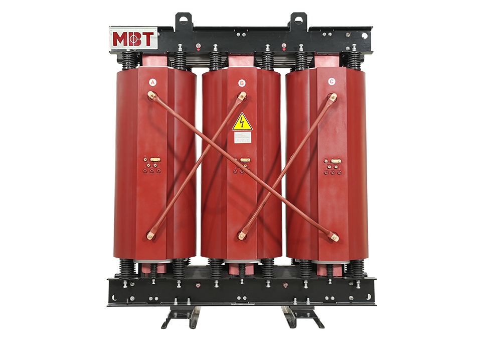
If you have a difficulty in selecting the right transformer for your project, MBT will be willing to give you the best advice. Please contact us freely for the best support.