
THE DEFINITION AND THE ADVANTAGES OF INSTRUMENT TRANSFORMER


THE DEFINITION AND THE ADVANTAGES OF INSTRUMENT TRANSFORMER
What is Instrument Transformer?
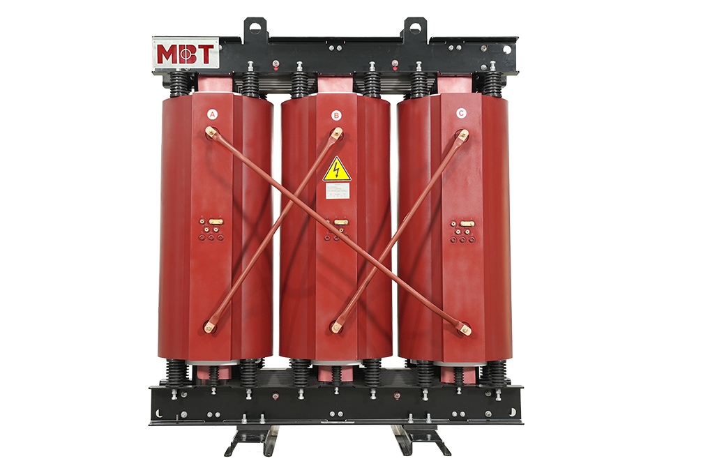
Instrument Transformers are a type of transformer used in an AC system to measure electrical quantities as voltage, current, power, energy, power factor, frequency. Instrument transformers are also equipped with protective relays to protect the power system.
Instrument transformers have the basic function of reducing the AC System voltage and current. The current and voltage level of the power system is relatively high. It is very difficult and costly to design the measuring instruments to measure such high-level current and voltage. Generally, measuring instruments are designed for 110 V and 5 A
The measurement of such very large electrical quantities can be made possible by using the Instrument transformers equipped with these small rating measuring instruments. Thus, these instrument transformers are very well-known in modern power systems.
Related article:
What Is Electrical Transformer?
Transformer Parts and Functions
Advantages of Instrument Transformers
- A small rating measuring instrument can be used to measure the large current and voltage of the AC Power system i.e., 5 A, 110 – 120 V.
- Measuring instruments can be standardized by using instrument transformers. Which results in the reduction in the cost of measuring instruments. If the measuring instruments are damaged, they can be replaced easily by healthy standardized measuring instruments.
- Instrument transformers provide electrical isolation between measuring instruments and high voltage power circuits, which reduces the electrical insulation requirement for protective circuits and measuring instruments and also assures the safety of operators.
- Several measuring instruments can be linked through a single transformer to a power system.
- Due to the low current and voltage levels in measuring and protective circuits, there is low power consumption in measuring and protective circuits.
Types of Instrument Transformers
There are 2 types of instrument transformers as follows:
Current Transformer (C.T.)
A current transformer is a type of transformer used to reduce the current of a power system to a lower level to make it feasible to be measured by a small rating Ammeter (i.e. 5A ammeter). A typical connection diagram of a current transformer is shown as follows.
Primary of C.T. has very few turns. bar primary is sometimes also used. Primary is linked in series with the power circuit. Therefore, sometimes it is also called a series transformer. The secondary is having a large no. of turns. The secondary is linked directly to an ammeter. As the ammeter is having very small resistance. Hence, the secondary current transformer works almost in short-circuited conditions. One terminal of the secondary is earthed to avoid the large voltage on the secondary with respect to the earth. Which in turn reduces the chances of insulation breakdown and also protects the operator against high voltage. Furthermore, before disconnecting the ammeter, the secondary is short-circuited through a switch ‘S’ as shown in the above figure to avoid the high voltage build-up across the secondary.

Potential Transformer (P.T.)
The potential transformer is a type of transformer used to reduce the voltage of the power system to a lower level to make it feasible to be measured by a small rating voltmeter i.e. 110 – 120 V voltmeter. A typical connection diagram of a potential transformer is showing in the following figure.

Primary of P.T. has large no. of turns. Primary is linked across the line (generally between on earth and line). Therefore, it is sometimes also called the parallel transformer. Secondary of P.T. has few turns and is linked directly to a voltmeter. As the voltmeter has a large resistance. Thus, the secondary of a P.T. works almost in open-circuited condition. One earthed terminal of secondary of P.T. is to maintain the secondary voltage with respect to earth.
What are the differences between C.T. and P.T?
Few differences between C.T. and P.T. are as follows:
|
Sl. No. |
Current Transformer (C.T.) |
Potential Transformer (P.T.) |
|
1 |
linked in series with a power circuit. |
linked in Parallel with the Power circuit. |
|
2 |
The secondary is linked to Ammeter. |
The secondary is linked to Voltmeter. |
|
3 |
Secondary operates almost in short-circuited conditions. |
Secondary operates almost in open-circuited conditions. |
|
4 |
The primary current is subject to on power circuit current. |
The primary current is subject to secondary burden. |
|
5 |
Primary current and excitation vary over a wide range with a change of power circuit current |
Primary current and excitation variations are restricted to a small range. |
|
6 |
One terminal of the secondary is earthed to avoid the insulation break down. |
One terminal of secondary can be earthed for safety. |
|
7 |
The secondary is never open-circuited. |
Secondary can be used in open circuit conditions. |