
Single-Phase Transformer Connections


Single-Phase Transformer Connections
A single-phase transformer is connected into a typical arrangement. The secondary winding is arranged in two sections with the aim of providing flexibility for connection. The number of turns and the voltage of Each are the same. Two primary leads (H1, H2) are brought out from the top through porcelain bushings. Three secondary leads (X1, X2, X3) are brought out through insulating bushings on the side of the tank, one lead from the center tap (neutral) (X2) and one from each end of the secondary coil (X1 and X3).
Connections, as shown, are typical of services to homes and small businesses. This connection provides a three-wire service that permits adequate capacity at minimum cost. The neutral wire (X2) (center tap) is grounded. A 120-volt circuit is between the neutral and each of the other leads, and a 240-volt circuit is between the two ungrounded leads.
![]()
Picture 1: Single-Phase Transformer
Parallel Operation of Single-Phase Transformers for Additional Capacity
In perfect parallel operation of two or more transformers, the current in each transformer will be proportional to the transformer capacity and the arithmetic total will be equal to half of the total current. In practice, this is rarely achieved because of small variations in the transformer. However, there are conditions for transformers to operate in parallel. They are:
- Using Any combination of positive and negative polarity transformers. However, in all cases, It is required to follow numerical notations both primary and secondary connections. That is H1 linked to H1, H2 linked to H2, and X1 linked to X1, X2 linked to X2, X3 linked to X3. Note that each subscript number on a transformer must be linked to the identical subscript number on the other transformer as shown in Picture 2.
- Tap settings must be the same.
- Voltage ratings must be the same; this, of course, makes the turns ratios also the same.
- The percent impedance of one transformer must be from 92½% to 107½% of the other. Otherwise, circulating currents between the two transformers would be excessive.
- Frequencies must be the same. The standard frequency in the United States is 60 hertz and usually will not present a problem.
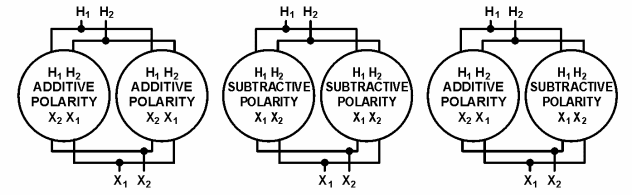
Picture 2: Single-Phase Paralleling
CAUTION: With positive and negative polarity transformers, the location of X1 and X2 connections on the tanks will be reversed. Care must be exercised to ensure that terminals are connected, as stated above. See Picture 2.
One will notice, from the above requirements, the size of that paralleled transformers is not the same. However, their size must be nearly the same to meet the percent impedance requirement. Most utilities will not parallel transformers if they are more than one standard kVA size rating different from each other, otherwise, circulating currents are excessive.