Potential Transformer | MBT Transformer
Potential Transformer: Definition, Construction, Types, and Purpose of using
A potential transformer (PT), or a Voltage Transformer (VT) is an Instrument Transformer used to measure voltage. It is specially designed to maintain the correct voltage phase angle reference between the Instrument Transformer's source and output and excellent voltage regulation to obtain precise voltage measurements. When used with a Current Transformer (CT), precise power measurements can be made.
Table of Contents
1. What is a Potential Transformer?
2. Principle of operation and the basic structure of the Potential Transformer
4. Connection of potential transformer
5. Types of Potential Transformer
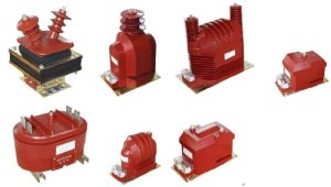
a. Outdoor potential transformer
b. Indoor Potential Transformers
6. Ratio and Phase Angle Errors of Potential Transformer
7. The burden of a Potential transformer
8. Phasor diagram of a Potential transformer
9. Applications of Potential Transformer
1. What is a Potential Transformer?
A potential transformer can be defined as an instrument transformer used to convert voltage from a higher value to a lower value. This transformer drops the voltage to a safe limit value that can be easily measured with conventional low-voltage instruments such as a voltmeter, wattmeter and watt-hour meter, etc.
2. Principle of operation and the basic structure of the Potential Transformer
The basic construction and operation principle of this transformer is similar to that of a standard electric transformer. Typically, the potential transformer is abbreviated as PT.
The primary winding consists of many turns connected through the high-voltage side or line on which the measurements must be made or protected. The secondary winding with a lower number of turns is connected to the voltmeter or the wattmeter's potential coils, energy meter, relay, and other control devices. These can be single-phase or three-phase potential transformers. Regardless of the primary voltage rating, they are designed to have a secondary output voltage of 110 V.
Since the voltmeter and the other meters' voltage coils are of high impedance, a small current flows through the PT's secondary winding. Therefore, the PT acts as a conventional two-winding transformer without load. Due to this low load (or burden) on PT, the PT's VA rating is low and ranges from 50 to 200 VA. On the secondary side, one end is connected to the ground for safety reasons, as shown in the figure.
Similar to ordinary transformers, the transformation ratio is specified as
V1 / V2 = N1 / N2
From the above equation, if you know the voltmeter reading and transformation ratio, you can determine the high voltage side voltage.
3. Construction
Compared with conventional transformers, potential transformers or PTs use larger conductor sizes and cores. PT was designed to ensure higher accuracy, and therefore, at the time of design, material' economics was not considered the central aspect.
PT is built with an exceptionally high-quality core that operates at a lower flux density for a small magnetizing current to minimize load loss. Both core and shell construction is preferred for PT. For high voltage, core type PT is used while the shell type is selected for low voltage.
To reduce leakage resistance, coaxial coils are used for both primary and secondary windings. To reduce insulation costs, a low voltage secondary winding is placed next to the core. And for high voltage PTs, the high voltage primary is divided into sections of the coil to reduce the insulation between the coil layers. For these coils, cambric tape and vanishing cotton are used as coatings. In between the coils, a rigid fiber separator is used.
They are carefully designed to have a minimum phase difference between the input and output voltages and maintain a minimum voltage ratio to the load change. The oil-filled PTs are used for high voltage grades (above the 7KV range). In such PTs, the oil-filled bushing is provided to connect the main lines.
4. Connection of potential transformer
The potential transformer is connected in parallel with the circuit. The transformer primary windings are connected directly to the supply circuit whose voltage is to be measured. The PT transformer's secondary terminals are connected to a measuring instrument such as a voltmeter, a wattmeter, etc. The secondary windings of a transformer are magnetically coupled through the primary winding.
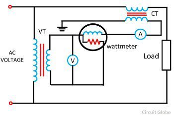
Connection of a portential transformer
The PT transformer's primary terminal is rated for 400V to several thousand volts, and the secondary terminal is always rated for 400V. The ratio of the primary voltage to the secondary voltage is called the ratio of variation or turn ratio.
5. Types of Potential Transformer
a. Outdoor potential transformer
These can be either single-phase or three-phase voltage transformers available for different operating voltage ranges used for outdoor measuring and transition applications. Up to 33KV, these are single-phase and three-phase electromagnetic transformers. The above outdoor single-phase 33KV transformer can be of two types: an electromagnetic voltage transformer and a capacitive type voltage transformer (CVT).
- Electromagnetic or Wound Type Conventional Potential Transformer
They are similar to conventional oil-filled wire wound transformers. The figure below shows the electromagnetic type of PT in which the tank is connected to line terminals. A plug is provided on the tank to fill the oil, and the tank is mounted on an insulating support.
At the base, ground connector and oil drain plug are provided. In this case, the primary is connected between two phases or between a single-phase and earth. So one end of the main unit is connected to the mainline at the top, and the other end is given at the bottom and grounded to the other grounding terminals.
The secondary terminals consist of an earth terminal located in the terminal box at the bottom; furthermore, they are connected to metering circuits and relays. They are used up to or below 132 kV operating voltage due to the insulation aspects.
- Capacitive Voltage Transformer (CVT)
It is a capacitance divider that is connected between the phase of the mainline and ground. This can be a coupling capacitor or a CVT bushing type. These two are less or electrically similar, but the difference is that capacitance formation further decides their rated burden (or load).
The coupling capacitor type consists of a stack of series-connected capacitors made up of oil-impregnated paper and aluminum foil. For the desired primary and secondary voltages, the primary and secondary terminals are connected across capacitors.
The CVT bushing type uses the condenser type bushing provided with the tapping. CVT is also used to communicate with power line providers and is, therefore, more economical.
b. Indoor Potential Transformers
They are also available as single or three-phase PT, magnetic, the cast type. The mounting mechanism can be fixed or pulled kind. In this type of PT, all primary winding parts are insulated from the earth at its rated insulation capacity. They are designed to operate relays, measuring instruments, and other control devices in-home service with high precision.
Depending on the function, a PT transformer or a voltage transformer is classified into a measuring voltage transformer and a protective voltage transformer.
6. Ratio and Phase Angle Errors of Potential Transformer
In an ideal potential transformer, the primary and secondary voltages are precisely proportional to the primary voltage and exactly in phase opposition. But this cannot in practice be achieved due to the drop in primary and secondary voltages. Hence, both primary and secondary voltages are introduced into the system.
- Voltage Ratio Error
The indicated voltage ratio error is related to the measured voltage, and it is given by the formula, as shown below.

Where Kn is the rated ratio, that is the ratio between the rated primary voltage and the rated secondary voltage.
- Phase Angle Error
The phase angle error is the error between the exactly reverse-phase secondary terminal voltage and the primary terminal voltage.
The increases in the number of devices in the relay connected to the transformer's secondary increase the transformer's error.
7. The burden of a Potential transformer
The burden is the total external volt-amp load on the secondary at the nominal secondary voltage. The PT's nominal load is that the VA burden should not be exceeded if the transformer is operated with its rated accuracy. The rated burden is listed on the nameplate.
The limit load or the maximum load is the maximum VA load at which a potential transformer will operate continuously without overheating its windings above the permissible limit. This burden is many times larger than the rated burden.
8. Phasor diagram of a Potential transformer
The phasor diagram of the transformer is shown in the figure below.
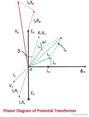
Where, Is – secondary current
Es – secondary induced emf
Vs – secondary terminal voltage
Rs – secondary winding resistance
Xs – secondary winding reactance
Ip – Primary current
Ep – primarily induced emf
Vp – primary terminal voltage
Rp – primary winding resistance
Xp – primary winding reactance
Kt – turn ratio
Io – excitation current
Im – magnetizing component of Io
Iw – core loss component of Io
Φm – main flux
Β- phase angle error
The main flux is taken as a reference. In the instrumental variable, the primary current is the vector sum of the current excitation Io and the current equivalent to the Is the inversion multiplied by the ratio 1 / kt. Vp is the voltage applied to the primary terminal of the potential transformer.
The voltage drop due to resistance and the primary current's reactance due to the primary current is given by IpXp and IpRp. When the voltage subtracts the potential transformer's primary voltage, the inductive emf will mainly appear on the terminals.
This main emf of the transformer will transform into the secondary coil by inducing each other and converting into secondary, causing emf Es. This emf will decrease by the resistance and reactance of the secondary winding, and the resulting voltage will appear across the secondary terminal voltage, and Vs denotes it.
9. Applications of Potential Transformer
It is used for metering purposes.
-
To protecting the feeders.
- To protecting the impedance of the generator.
- For generator and feeder synchronization.
Transformers are used in the protective relay scheme because the protective device's potential windings are not connected directly to the system in the case of high voltage. Therefore, it is necessary to reduce the voltage and insulate the protective device from the primary circuit.


