
Open Circuit and Short Circuit Test of Transformer


Open Circuit and Short Circuit Test of Transformer
The open-circuit test and the short-circuit test are performed on a transformer to determine the equivalent circuit of the transformer, the voltage regulation of the transformer, and the efficiency of the transformer.
Table of Content
1. Short Circuit Test on Transformer
2. Open Circuit Test on Transformer
1. Short Circuit Test on Transformer
The connection diagram for the short circuit test on the transformer is shown in the figure below. A wattmeter, voltmeter, and ammeter are linked to the HV side of the transformer as shown. A low voltage of around 5-10% is applied to that HV side with the help of a variac. We short-circuit the LV side of the transformer. Now with the help of variac applied voltage is slowly increased until the wattmeter, and an ammeter gives a reading equal to the rated current of the HV side.
After reaching the rated current of the HV side, we record all three instrument readings (Voltmeter, Ammeter, and Watt-meter readings). The ammeter reading gives the primary equivalent of full load current IL. As the voltage applied for full load current in a short circuit test on the transformer is quite small compared to the rated primary voltage of the transformer, the core losses in the transformer can be taken as negligible here.
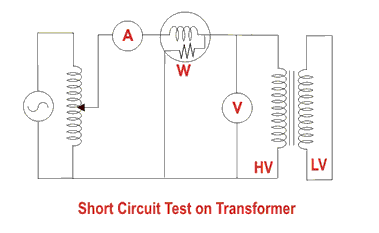
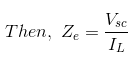
The voltmeter reading is Vsc. The watt-meter reading indicates the input power during the test. As we have short-circuited the transformer, there is no output; hence the input power here consists of copper losses in the transformer. Since the applied voltage Vsc is a short circuit voltage in the transformer and hence it is quite small compared to the rated voltage, so, we can neglect the core loss due to the small applied voltage. Hence the wattmeter reading can be taken as equal to copper losses in the transformer. Let us consider the wattmeter reading is Psc.
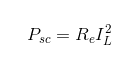
Where Re is the equivalent resistance of the transformer.
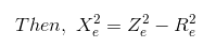
If, Ze is the equivalent impedance of the transformer.
Therefore, if the equivalent reactance of the transformer is Xe.
These values are referred to as the HV side of the transformer as the test is conducted on the HV side of the transformer. These values could easily be converted to the LV side by dividing these values with the square of the transformation ratio.
Hence the short-circuit test of a transformer is used to determine copper losses in the transformer at full load. It is also used to obtain the parameters to approximate the equivalent circuit of a transformer.
2. Open Circuit Test on Transformer
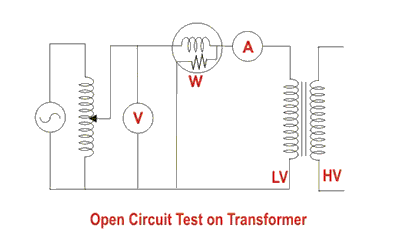
The connection diagram for the open circuit test on the transformer is shown in the figure. A voltmeter, wattmeter, and ammeter are connected on the LV side of the transformer as shown. The voltage at rated frequency is applied to that LV side with the help of a variac of variable ratio autotransformer.
The HV side of the transformer is kept open. Now with the help of variac, the applied voltage gets slowly increased until the voltmeter gives a reading equal to the rated voltage of the LV side. After reaching the rated LV side voltage, we record all three instruments reading (Voltmeter, Ammeter, and Wattmeter readings).
The ammeter reading gives the no load current Ie. As no load current Ie is quite small compared to the rated current of the transformer, the voltage drops due to this current can be taken as negligible.
Since voltmeter reading V1 can be considered equal to the secondary induced voltage of the transformer, the wattmeter reading indicates the input power during the test. As the transformer is open-circuited, there is no output, hence the input power here consists of core losses in the transformer and copper loss in the transformer during no load condition. But as said earlier, the no-load current in the transformer is quite small compared to the full load current so, we can neglect the copper loss due to the no-load current. Hence, can take the wattmeter reading as equal to the core losses in the transformer.
Let us consider the wattmeter reading is Po.
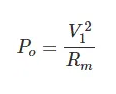
Where Rm is the shunt branch resistance of the transformer.
If, Zm is the shunt branch impedance of the transformer.
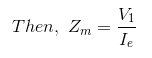
Therefore, if the shunt branch reactance of the transformer is Xm,
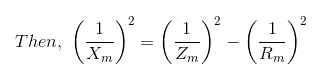
These values are referred to as the LV side of the transformer due to the tests being conducted on the LV side of the transformer. These values could easily be referred to as the HV side by multiplying these values with square of the transformation ratio.
Therefore it is seen that the open circuit test on the transformer is used to determine core losses in the transformer and parameters of the shunt branch of the equivalent circuit of the transformer.