
High Voltage Transformers


HIGH VOLTAGE TRANSFORMERS
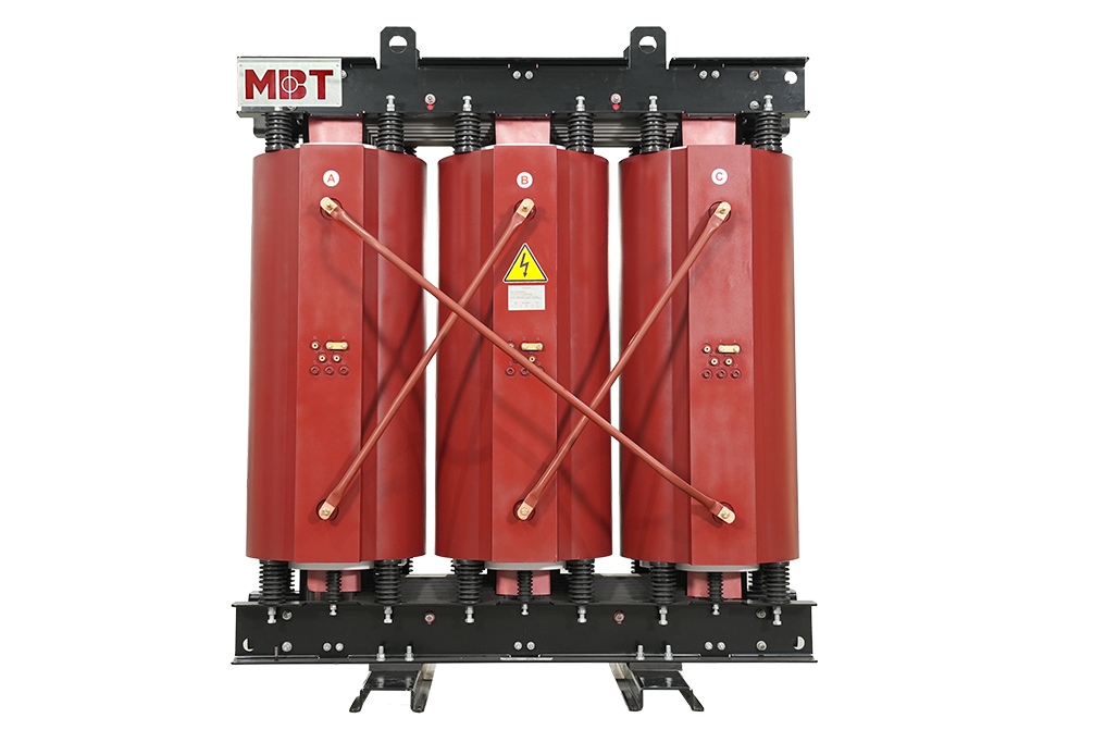
A high voltage transformer is a kind of transformer operating at a high voltage level. This transformer is designed to use in high voltage labs with the aim of testing.
It has to withstand surges and transient voltages during its normal operation when the insulation under test breaks down. In order to withstand this impulse voltage, its insulation must be carefully designed. It is a usually single-phase core-type transformer.
This type of transformer is generally immersed in oil. Bakelite sheets are used for separating low-tension and high-tension windings. The high voltage transformers which are used for HV cable testing also are required to supply sufficient electric current. Therefore, a lot of heat can be generated, the cooling system of these transformers is very carefully designed. It is necessary to take special care to ensure proper transformer voltage regulation. With the aim of testing the insulator, the required current is very less but, while the insulator breaks down during testing, a huge current will flow through the transformer. In order to limit this current, a high resistance is linked in series with the transformer. As insulation testing does not need a high current, high voltage transformers used for this purpose are not required to have a high kVA rating.
Based on the ratings of the transformer, there are various testing purposes. The below table shows the ratings of the transformer up to 500kv voltage, typically only a single unit of the high voltage transformer is used.
|
SL |
Purposes |
Capacity |
Maximum Voltage |
|
1. |
Routine test for electric motors & switch gears |
small |
2 to 3 KV |
|
2. |
Insulation testing |
10 to 20 kVA |
50 KV |
|
3. |
Routine test of cable |
50 kVA |
10 to 30 KV |
|
4. |
Extra high voltage transformer & insulators testing |
20 to 50 kVA |
100 – 200 KV |
|
5. |
String insulator testing |
0.5 to 1 kVA per KV |
500 to 2000 KV |
|
6. |
High voltage cable testing |
100 to 500 kVA |
100 to 500 KV |
For the ratings of the transformer more than 500k, a single transformer is not used for the economy (the size is much too big). In these situations where more than 500 kV is required, two units are arranged in series to produce the required voltage.
The below figure shows the typical cascading connection of two transformers.

Low voltage is provided to the low voltage winding of a step-up transformer 1 as shown in the above figure. The tank of this transformer is insulated from the earth.
The secondary of this transformer is linked to the earthed tank and another end comes out through a high voltage bushing. The bushing is so specially manufactured and designed, that it can be subject to full secondary high voltage, in respect of earthed potential of the transformer tank.
Another tapping terminal also runs through this high voltage bushing. The tapping terminal ends and the high voltage end is linked across the primary of the second transformer.
The tank of the second transformer is linked to one end of the secondary winding. Unlike the first transformer, the tank of the second transformer is not earthed. It is earthed for the full secondary voltage of the transformer. One end of the high voltage or secondary winding of the second transformer is earthed and another end alone comes out from the high voltage bushing for feeding high voltage to insulators and the equipment under testing.
The induction regulator method is most suitable for the high voltage transformer, used for power cable testing purposes. Because its gradual voltage variation at loads of any magnitude is advantageous for such work.