
Conservator Tank of a Transformer


Conservator Tank of a Transformer
The Conservator Tank of a transformer is defined simply as a cylindrical tank mounted on the roof of the transformer main tank. It is used to provide enough space for the oil in the transformer to spread after heating.
The main function of the conservator Tank
When the transformer is loaded and when the ambient temperature rises, make the volume of oil inside the transformer increase. A conservator tank of the transformer supplies adequate space to this expanded transformer oil. It also is designed as a reservoir for transformer insulating oil.
Construction of Conservator Tank
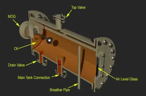
It is designed as a cylindrical tank or oil container closed from both ends. It is designed with One large inspection cover on either side of the container to make maintenance and cleaning easy inside of the conservatory. Conservator pipe, i.e. pipe comes from main transformer tank, is placed inside the conservator from the bottom part. The top of the conservator pipe inside the conservatory is equipped with a cap.
This pipe is supplied with a cap because this design any kind of oil waste to enter into the main tank from the conservator. Generally, silica gel breather fixing pipe enters into the conservatory with the help of the top part of the tank.
If it enters from the bottom part, it must be projected above the oil level inside the conservator. This arrangement ensures that oil does not enter the silica gel breather even at the highest operating levels.
With the help of a breather, the silica gel goes through the fixed pipe to the Conservator Tank. When this pipe goes through the base, it should be well estimated at the top of the oil level in the tank. This adjustment ensures that the transformer oil does not inhale silica gel even at the maximum operating level.
Working Principle of Conservator Tank
Due to load and ambient temperature, the volume of transformer insulating oil increases, and then the expanded oil occupies a part of the free space above the oil level inside the conservator.
Accordingly, the corresponding amount of air in that space is pushed through the breathing tube. On the other hand, when the load of the transformer decreases, the transformer is switched off, and when the ambient temperature decreases, the oil inside the transformer contracts. This causes outside air to enter the transformer's conservator tank through the silica gel breathing.
Atmoseal Type Conservator
In this type of conservator of the transformer, there is an air cell made of NBR material fitted inside the conservator reservoir. The silica gel breather is linked to the top of this air cell. The oil level in the power transformer rises and falls depending on this air cell deflated and inflated. When the air cell gets deflated the air in the air cell comes out with the help of its breather and on the other hand, if the cell is inflated the outside air enters inside through a breather.
This arrangement avoids direct contact of oil with air, thereby reducing the aging effect of the oil.
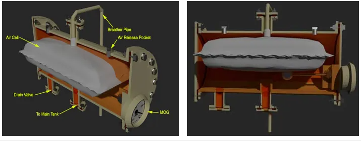
Oil totally fills in the space available outside the cell in the conservator tank. Air vents are supplied on the top of the conservator for venting accumulated air outside the air cell.
The pressure in the air cell must be maintained at 1.0 PSI.
Diaphragm Sealed Conservator
The Diaphragm is used as a barrier between the conservator outside air as well as the transformer. In such a situation the conservator tank of the transformer can be designed with two hemispherical parts.
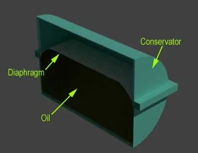
In this case, the conservator of the transformer is made of two semicircular halves and bolts. As oil spreads, the diaphragm is pushed up. The oil level indicator shows the position of the diaphragm i.e. magnetic oil gauge (Here MOG is not shown in the figure above) as the rod of this MOG is linked to the diaphragm. When the oil level decreases in the conservatory, the diaphragm deflects and the atmospheric air fills the free place. This air is sucked through a silica gel breather linked to the center of the transformer’s conservator tank. (Here silica gel breather is not shown in the figure above) This type of conservator has one advantage over the air cell conservator. If gas is pressurized to a high level, it gets dissolved in oil.
Over a period of time, the volume of gas in the oil reaches the saturation point. If at this stage, the load of the transformer is suddenly reduced or the ambient temperature decreases severely, the pressure drops, oil becomes supersaturated and the gas bubbles will be evolved. If a pump is connected to the cooling circuit, it will help to generate the bubbles. These bubbles may cause insulation fault in the area of strong fields. (Here silica gel breather, MOG, Drain Valves, Air Pockets, Conservator to main tank connections is not indicated in the figure above.)