

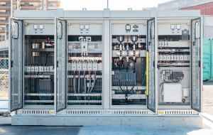
Solar Transformer for PV Projects



A solar transformer forms the electrical interface between PV inverters and the medium-voltage collection system or utility grid. It steps up the inverter’s AC output while supporting the voltage, insulation and grounding requirements of the project.
Although it operates on the same electromagnetic induction principle as a conventional transformer, variable solar generation and inverter-based operation create additional demands related to harmonics, cyclic loading, voltage coordination and outdoor conditions. This article explains the transformer’s role, main components and working principle, followed by the key requirements for sizing, design, protection and monitoring.
What Is a Solar Transformer and What Does It Do?
In utility-scale and large commercial solar projects, PV arrays generate DC power, which is converted into AC power by inverters. Installed downstream of the inverter, a solar transformer steps up the AC output voltage to the level required by the medium-voltage collection system or grid connection point.
PV arrays → Inverters → Solar transformer → Medium-voltage collection system → Grid connection point
Depending on the system design, the transformer may also provide galvanic isolation and establish the required winding and grounding interface between the inverter system and the electrical network. Its rated capacity, voltage ratio, vector group and insulation level must therefore be selected according to the inverter characteristics and project-specific grid requirements.
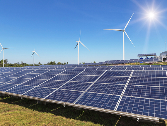
Solar Power System In Ninh Thuan – Viet Nam
Main Components and Working Principle
A solar transformer has the same fundamental structure as a conventional transformer, but its configuration must be adapted to the inverter characteristics, voltage levels and operating conditions of the solar project.
Main Components
The principal components include:
- Magnetic core: Provides a path for the magnetic flux required for voltage transformation.
- Inverter-side and grid-side windings: Receive AC power from the inverter and deliver it at the required higher voltage. Multiple inverter-side windings may be used in certain project designs.
- Insulation and cooling system: Liquid-filled transformers use insulating fluid, while dry-type transformers use solid insulation and air cooling.
- Tank, enclosure, bushings and terminals: Protect the transformer and provide connections to the inverter system and medium-voltage network.
- Monitoring and protective devices: May include temperature sensors, oil-level indicators, pressure devices and a tap changer where required.
How Does a Solar Transformer Work?
PV arrays generate DC power, which is converted into AC power by the inverter. The AC current then enters the inverter-side winding and creates a changing magnetic flux in the transformer core. Through electromagnetic induction, this flux produces a voltage in the grid-side winding.
Based on the winding ratio, the transformer steps up the inverter output voltage to the level required by the medium-voltage collection system or grid connection point. It does not convert DC into AC or change the electrical frequency; these functions are handled by the inverter.
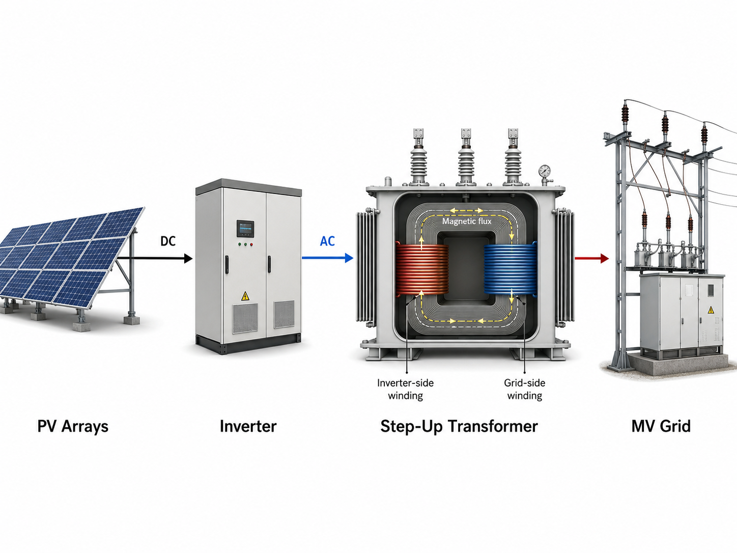
Solar Transformer Work
Solar Operating Conditions and Inverter Effects
Solar transformers operate with cyclic generation profiles and inverter-driven AC power. These conditions influence transformer loading, thermal performance and power quality throughout the operation of a solar project.
Variable and Cyclic Loading
Solar output changes with irradiance, temperature, cloud cover and daily or seasonal conditions. As a result, the transformer may operate from low load to peak output within the same day. These repeated load changes create thermal cycles in the windings and insulation system.
Low loading at night does not automatically justify selecting a smaller transformer or overloading it during peak generation. Thermal performance must be assessed according to the maximum expected inverter output, operating profile, cooling method and site conditions.
Harmonics, DC Bias and Inverter Output
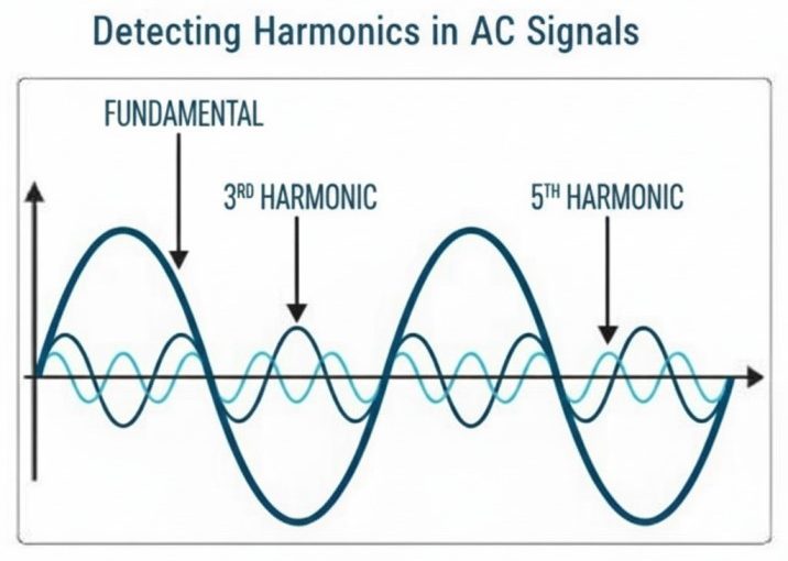
The fast-switching operation of inverters can introduce harmonic and high-frequency components into the AC waveform. These may increase winding and stray losses, resulting in additional transformer heating. System-level distortion should therefore be evaluated rather than relying only on the inverter’s stated THD value.
If residual DC injection exceeds the permitted limit, it can bias the transformer core and increase magnetizing current, vibration, noise and temperature. Transformer loading must also account for the inverter’s maximum apparent power, power-factor range, reactive-power capability and possible short-duration output peaks, not only its nominal active-power rating.
Sizing and Key Design Requirements
A solar transformer must be sized and configured according to the inverter system, applicable standards, grid-connection requirements and operating environment. Its rating should not be determined solely from the installed PV capacity or the nominal active-power rating of the inverters.
Key Factors in Transformer Sizing
The transformer rating should reflect the combined maximum apparent power of the connected inverters, including their power-factor range, reactive-power capability and expected output peaks. Harmonic heating, cyclic loading, ambient temperature, altitude and cooling conditions must also be considered.
Future expansion may be allowed for, but excessive oversizing should be avoided because it increases capital cost and no-load losses.
Voltage, Vector Group and Insulation Design
The voltage ratio must match the inverter output and medium-voltage collection system. Vector group and neutral grounding should follow inverter requirements, earth-fault protection and project-specific grid codes. No single winding configuration is suitable for every solar project.
Short-circuit impedance must be coordinated with fault-current limits, voltage regulation and system studies. Insulation coordination, temperature-rise limits, cooling method, guaranteed losses and short-circuit withstand capability must also meet the project requirements.
An electrostatic shield may reduce capacitive coupling and common-mode transients, but it does not eliminate harmonic currents. The intended energization and power-flow direction, tap range, inrush current and protection coordination must also be defined. Anti-islanding is provided by the inverter and protection system rather than the transformer itself.
Learn more about methods for connecting vector groups here
Protection, Monitoring and MBT Solar Solutions
Reliable protection and condition monitoring help solar transformers operate safely under cyclic loading, inverter-related disturbances and outdoor environmental conditions. The required devices should be selected according to the transformer type, rating and project protection scheme.
Protection and Remote Monitoring
Typical protection may include overcurrent, earth-fault, temperature and overvoltage protection. Differential protection can also be applied where required by the transformer rating and system design. Surge arresters should be coordinated with the transformer insulation level and grid-connection equipment.
Liquid-filled transformers may use oil-temperature, winding-temperature, oil-level, pressure and gas-detection devices. Dry-type transformers normally rely on winding-temperature sensors and thermal controllers. Alarm and trip contacts can be connected to the plant control system, allowing operators to detect overheating, pressure changes or other abnormal conditions remotely.
For large or remotely located solar farms, transformer data may be integrated into SCADA or another monitoring platform to support early fault detection and maintenance planning.
MBT Transformer Solutions for Solar Projects
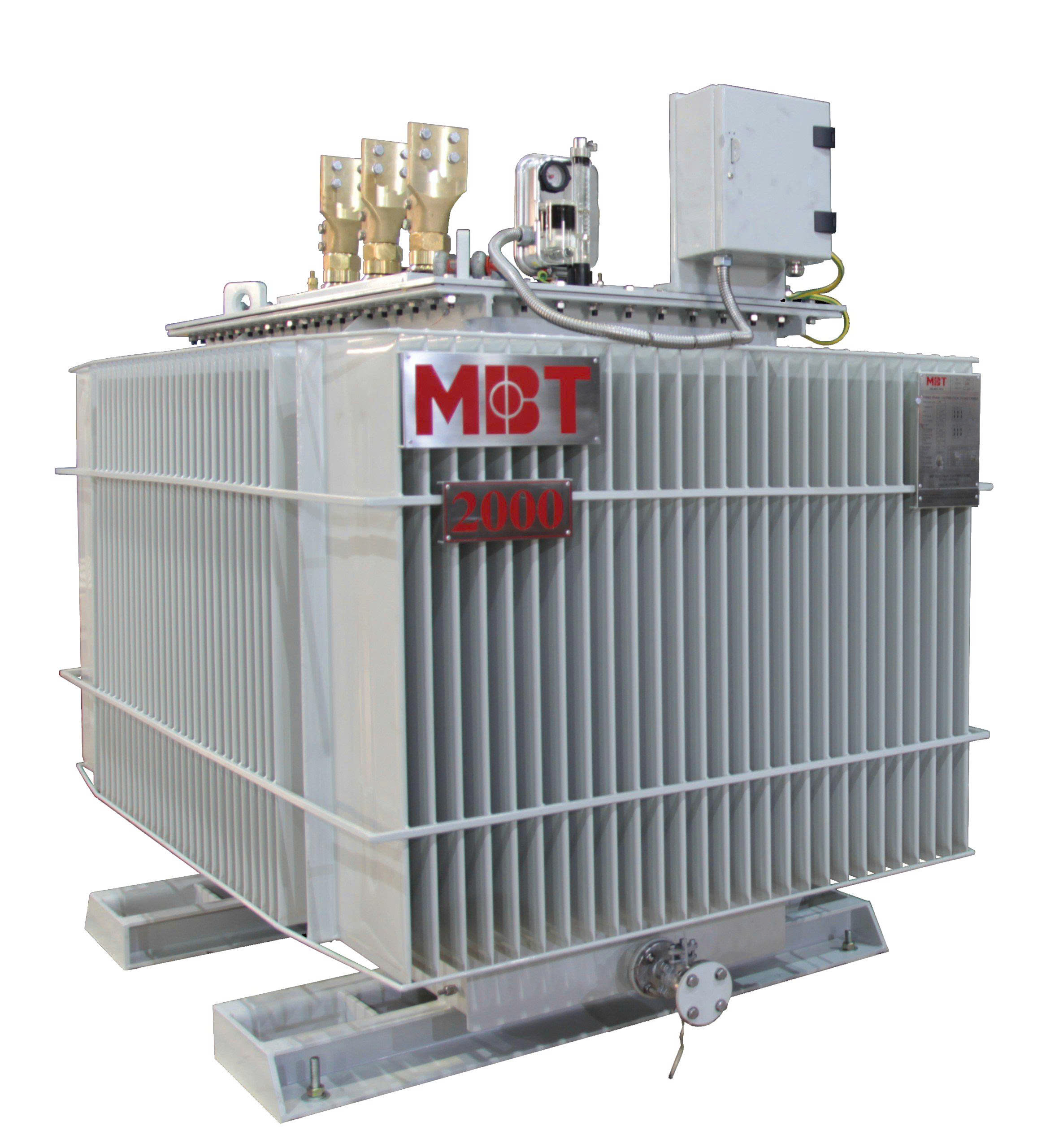
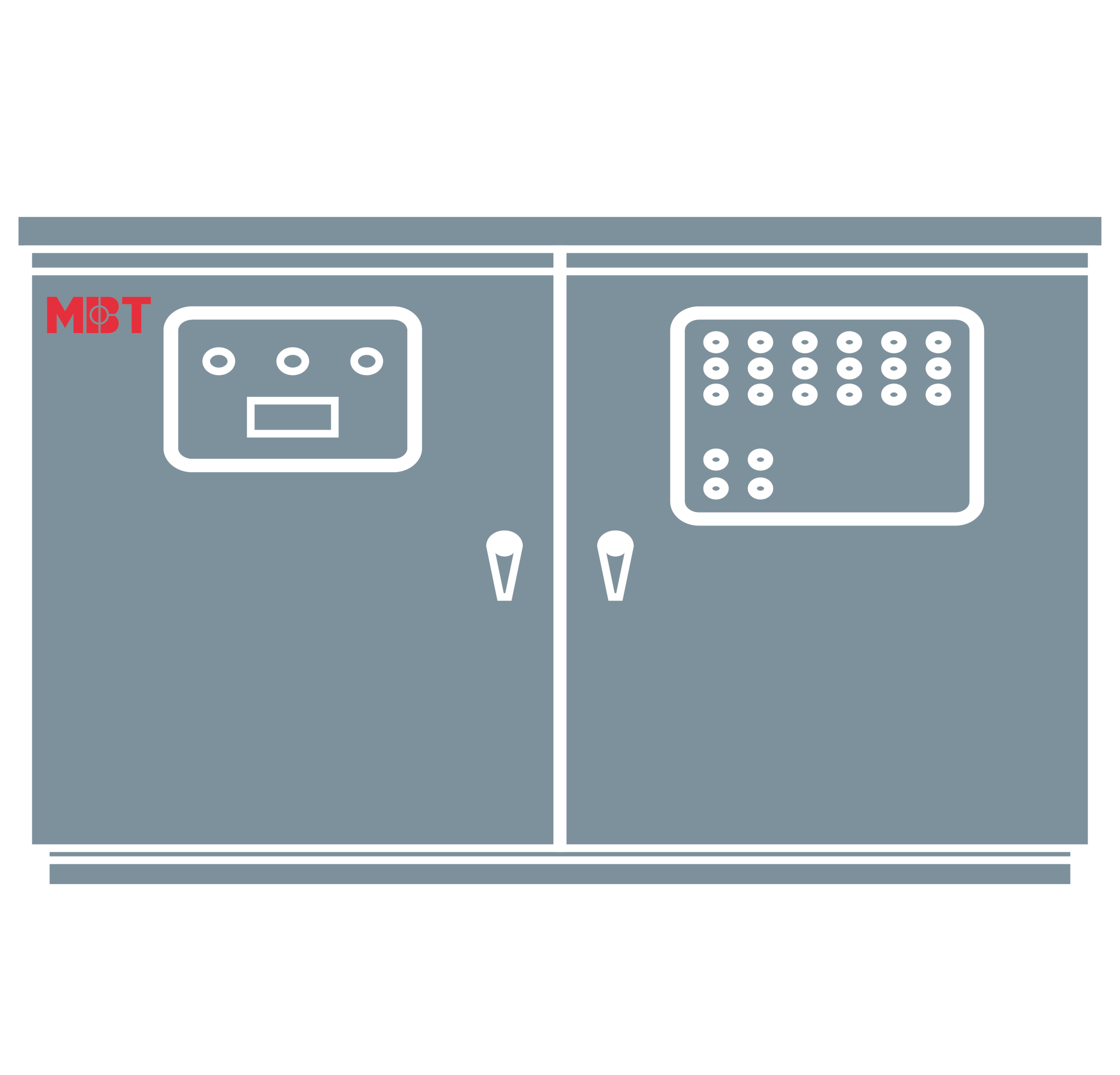
MBT provides oil-immersed transformers for outdoor and utility-scale applications, dry-type transformers for indoor or fire-sensitive locations, and pad-mounted or kiosk substations that integrate transformers with medium- and low-voltage switchgear.
Each solar transformer can be configured according to the required capacity, voltage ratio, vector group, guaranteed losses, cooling method, enclosure and protective accessories. Customers should provide inverter specifications, harmonic data, operating profile, grid-connection requirements and site conditions so that MBT can develop a suitable solution for the project.